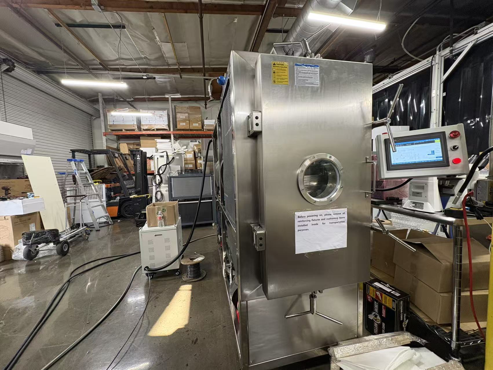
This United States peptide project began with a request for a high-density 13-shelf lyophilizer. The engineering work converted that request into a defined shelf stack, vial-planning boundary, vapor-load discussion, stoppering and controls scope, followed by two working days of on-site installation and commissioning support. The customer name, formulation and product results remain confidential and are not inferred here.
Real hydraulic stoppering footage used to explain a 13-shelf, 450 x 600 mm planning configuration and the boundary between geometric positions and an approved batch load.
Project configuration at a glance
| Application | Peptide lyophilizer configuration for an anonymized United States project |
|---|---|
| Equipment platform | Command F flexible-shelf pharmaceutical lyophilizer |
| Shelf arrangement | 13 product shelves, each 450 × 600 mm |
| Nominal product shelf area | 3.51 m² planning basis |
| Approximate planning clearance | About 58 mm; vial, stopper and loading clearances still require drawing review |
| On-site scope | Two working days for agreed installation, commissioning checks and operator handover — not customer IQ/OQ/PQ or process validation |
Vial geometry planning — not an approved batch load
| Planning vial | Nominal outside diameter | Geometric positions per 450 × 600 mm shelf | Status |
|---|---|---|---|
| 2R | 16 mm | 1,036 | Geometric planning value only |
| 3R | 16 mm | 1,036 | Geometric planning value only |
| 4R | 16 mm | 1,036 | Geometric planning value only; stopper clearance needs particular review |
| 6R | 22 mm | 540 | Geometric planning value only |
These are geometric planning values for a 450 × 600 mm shelf. They are not the customer load or a released batch quantity. Final positions can be lower after vial and stopper drawings, edge clearance, loading tools, probes, sampling and breakage allowance are reviewed.
The shelf count was an input, not the complete URS
Thirteen shelves increase nominal vial positions, but shelf count alone does not define a peptide batch. The review also needed the 450 × 600 mm shelf format, vial body and partially inserted stopper height, fill range, load map, stoppering travel, transfer method and documentation boundary.
The approximately 58 mm planning clearance makes this a high-density arrangement for confirmed small-vial formats. It is not a promise that every vial marketed as 2R, 3R, 4R or 6R will fit; actual component drawings and tolerances control the decision.
Geometric vial positions were kept separate from released batch quantity
The planning table uses vial outside diameter against the physical shelf surface. It helps compare shelf-count options before final component drawings are approved.
Actual batch quantity can be lower because of edge clearance, loading trays or tools, probe vials, sampling, stopper geometry, breakage allowance and the customer loading procedure. The values shown here are not the confidential project load and must not be used as production claims.
Condenser duty had to follow the real ice load and release rate
A larger vial-position envelope can carry more liquid, but condenser sizing cannot be selected from shelf area alone. Engineering must use intended loaded vial count, fill volume, solvent and water basis, total ice mass, expected primary-drying vapor rate and chamber-to-condenser conductance.
The condenser must be matched to both the quantity of ice and the rate at which vapor reaches it. The customer-specific condenser design is not published; the transferable rule is to confirm ice capacity, peak capture duty, refrigeration reserve and pressure-control behavior together.
Stoppering, controls and documentation were configuration decisions
The equipment file had to coordinate partially stoppered vial height, shelf movement, hydraulic stoppering, backfill or vacuum conditions, interlocks and representative container checks. These mechanical choices affect the usable shelf stack as directly as nominal vial diameter.
The agreed commissioning review covered the HMI sequence, alarms, refrigeration, vacuum and shelf-related functions. Electronic records, qualification deliverables, cleaning strategy and site procedures remain defined by the approved project scope and customer quality system.
Two working days described site support, not product qualification
After transport inspection and removal of shipping restraints, the site work addressed machine position, visible piping and wiring, service access, utilities, first start-up and the agreed equipment-function checks.
The two-working-day statement applies to installation and commissioning support. It does not claim completion of customer IQ, OQ, PQ, cleaning validation, peptide cycle validation, residual-moisture acceptance, potency, purity, stability or shelf-life work.
A comparable project should start with a configuration packet
Send vial and stopper drawings, fill range, intended minimum and maximum load, shelf map, total liquid and estimated ice mass, product-temperature limits, endpoint method and expected vapor-rate or cycle-development evidence.
Add cleanroom or barrier interfaces, loading and unloading method, stoppering and backfill basis, CIP/SIP expectations, utilities, data-integrity requirements, FAT/SAT and qualification responsibilities, and the installation access plan before freezing the commercial specification.