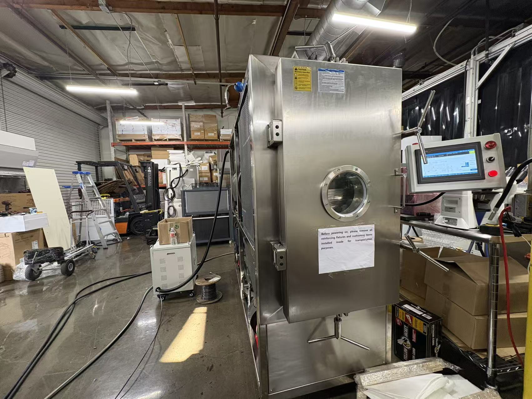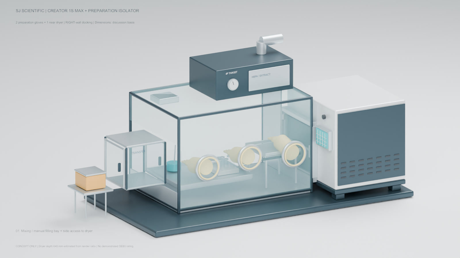
A compact lyophilizer can be connected to a negative-pressure preparation enclosure, but the connection becomes a pharmaceutical interface rather than a simple cabinet opening. The URS must separate proposed geometry from verified performance and define who owns the chamber seal, door sweep, pressure control, filtration, transfer sequence, cleaning boundary and acceptance evidence.
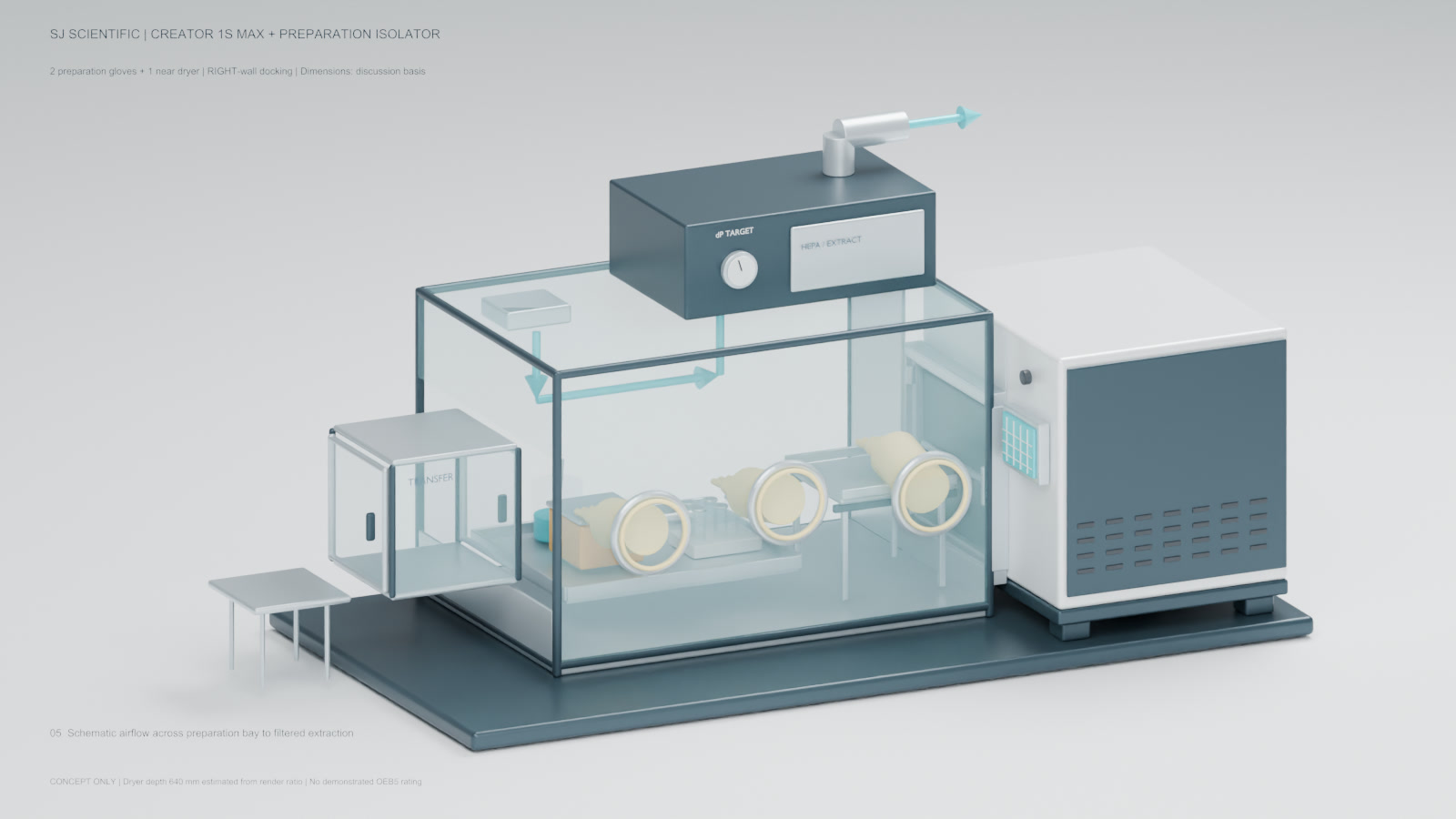
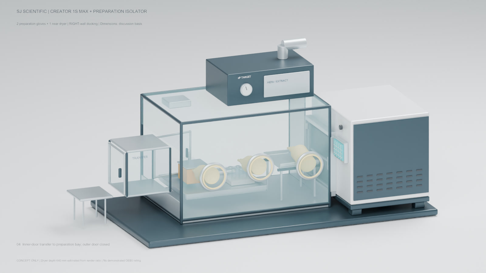
A 15-second engineering visualization used to identify containment-interface questions around pressure, filtration, transfer hatch, glove access and the external control bay. It is not CFD, smoke-study or containment-test evidence.
Interface and containment questions shown by the concept
Proposed configuration and evidence status
| Equipment basis | Creator 1S Max; 0.12 m2 shelf area; 300 x 400 mm fixed product shelf |
|---|---|
| Enclosure pressure target | Adjustable -10 to -30 Pa relative to room; preliminary target only |
| Filtration concept | H13 proposed; H14 option for assessment; final sizing and integrity testing required |
| Proposed top filter module | 700 x 450 x 250 mm |
| Provisional interface region | 500 x 410 mm with 50 mm axial allowance; not a released seal or net opening |
| Nominal equipment envelope | 2240 x 1100 x 1050 mm; excludes stand, exhaust stub and service/opening clearances |
| Gross enclosure envelope | 0.768 m3; free air volume remains unknown |
| Evidence status | Design visualization and proposed values; no installed or acceptance-test results |
Write containment intent before selecting a pressure number
The proposed -10 to -30 Pa range describes an adjustable negative-pressure target relative to the room. It is not an OEB criterion and does not establish control during transfers, glove movement, door operation, exhaust upset or filter loading.
The URS should identify the product and SDS, task quantities, exposure route, acceptable control objective, room relationship, upset response and the operating states that must be tested.
Define the lyophilizer interface as its own subsystem
The 500 x 410 mm region is provisional and the source marks 400 and 410 mm for different purposes. The interface bottom height is unresolved. None of these values should be converted into a released net opening or seal drawing.
Acceptance inputs include chamber-door sweep, adapter tolerance, gasket and clamp concept, cleanable surfaces, leakage path, carrier support, maintenance access and a responsibility boundary between the enclosure and lyophilizer.
Filter class is not a containment result
An H13 filter is proposed and H14 can be assessed, but filter classification does not size the fan or demonstrate enclosure performance. The enlarged 1200 x 800 x 800 mm enclosure needs a new air-balance calculation using the real free volume, leakage and operating states.
Specify filter integrity testing, pressure-control range and alarms, airflow indication, exhaust arrangement, recovery method and the representative tasks used for containment verification. Do not reuse an earlier purge-time estimate.
Keep aseptic product protection as a separate requirement
A negative-pressure enclosure is normally discussed around operator and room protection. Aseptic filling, sterile boundaries and product protection require their own contamination-control strategy and may conflict with simple inward-airflow assumptions.
Manual vial filling is an intended optional activity, not proof of an aseptic filling line. The URS must state whether the scope is non-sterile containment, aseptic processing, or a separately engineered combination.
Turn the concept into an acceptance matrix
A useful matrix links each URS item to design evidence, FAT or site test method, instrument, operating state and acceptance owner. Candidate rows include dimensions, glove reach, transfer-hatch interlock, pressure alarm, filter integrity, leakage, smoke visualization, cleaning access and supported carrier transfer.
IQ, OQ, PQ, cleaning validation, containment performance and product-process validation are distinct deliverables. A concept animation or factory visual cannot substitute for them.
Containment-interface URS FAQ
Does a -10 to -30 Pa enclosure meet OEB5?
Not by itself. OEB performance requires a defined hazard and task basis plus representative containment testing and acceptance criteria.
Does an H13 or H14 filter make the enclosure aseptic?
No. Filter selection, integrity, airflow and contamination control must be engineered and verified; operator containment and aseptic product protection are separate requirements.
Is the 500 x 410 mm interface a released opening size?
No. It is a provisional interface region. Seal geometry, net opening, interface height and door sweep remain to be confirmed.
Can the concept animation be used as FAT evidence?
No. It is a design communication aid. FAT and site acceptance need agreed procedures, calibrated instruments, operating states and recorded results.